
1/1


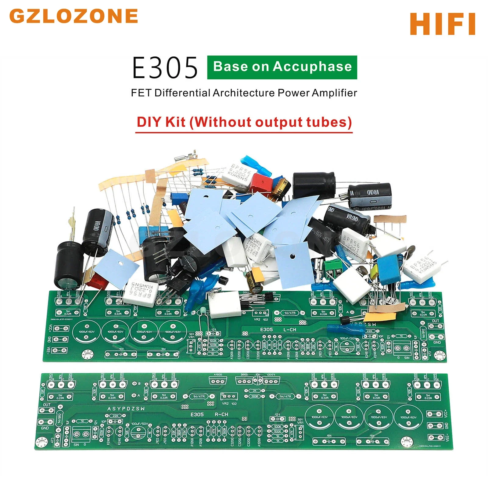
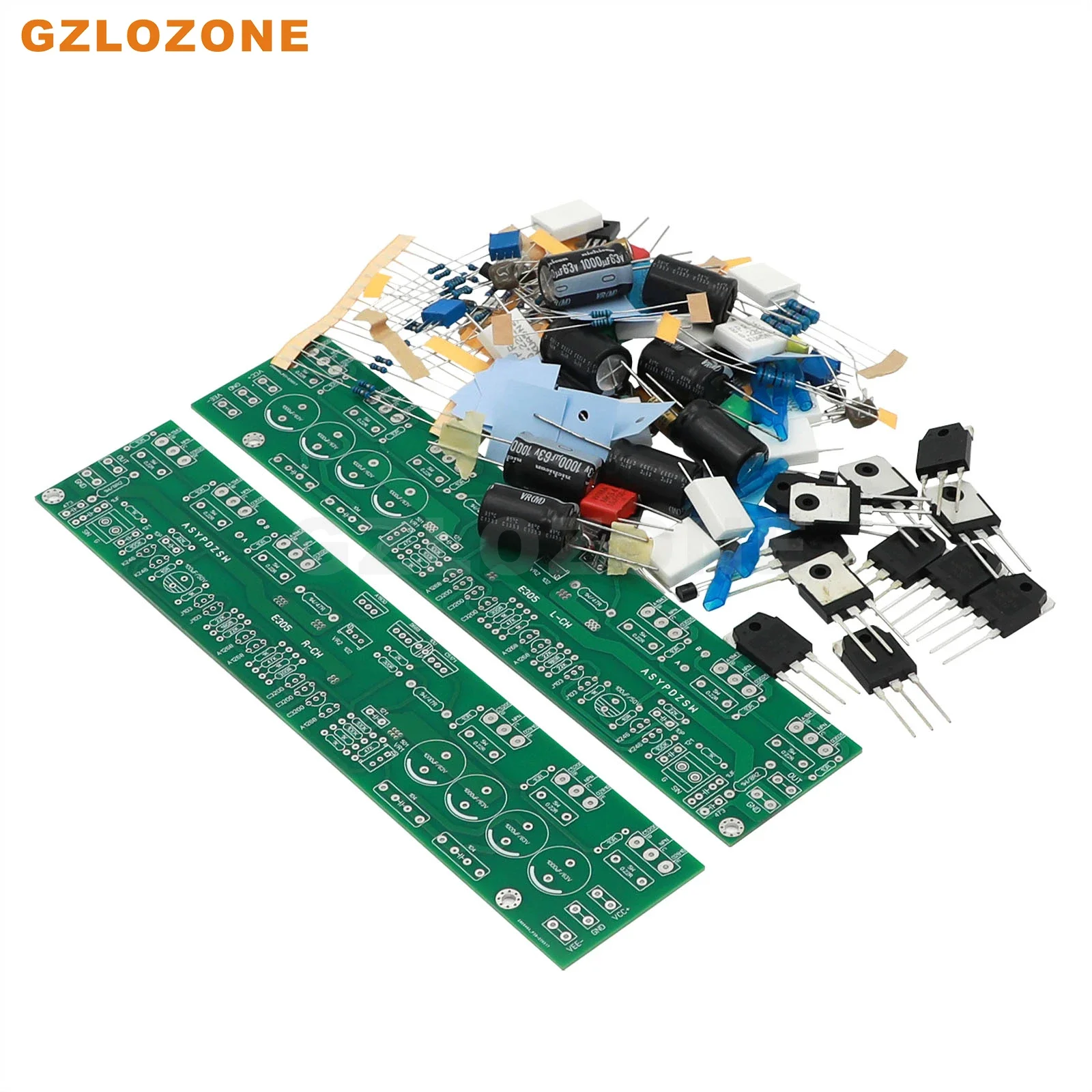
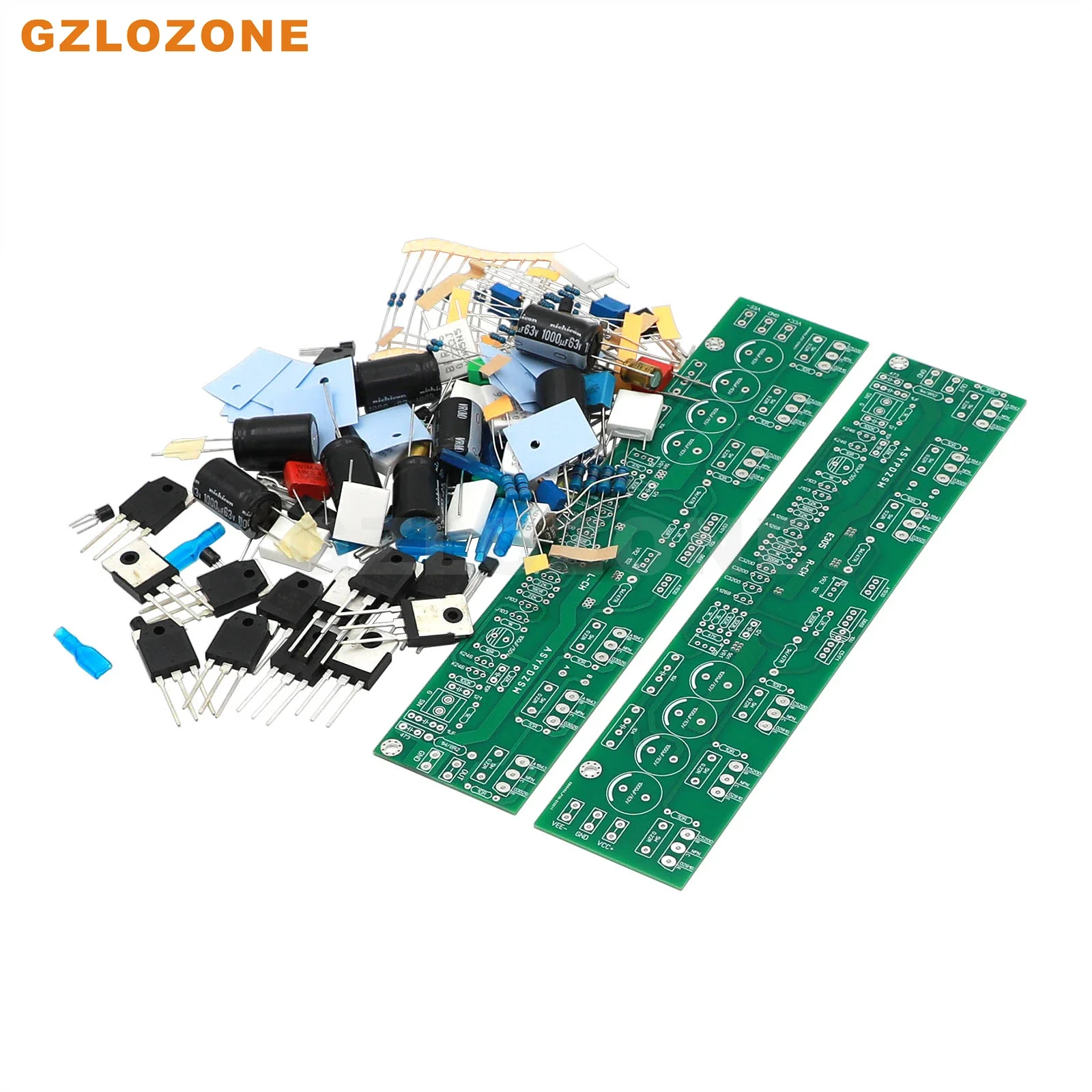
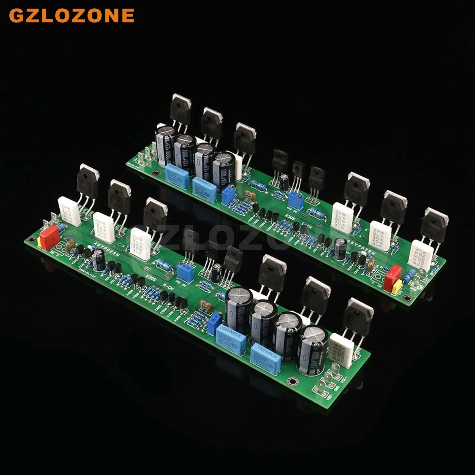
2CH HIFI E305 FET Differential Architecture Power Amplifier DIY Kit/Finished Board Base On Accuphase E-305 Circuit
(0 Reviews)


Introduction:
This circuit refers to the part of Accuphase E-305 pure power amplifier. It is well known that E-305 is a very expensive brand on the market. The input part of the power amplifier adopts FET diamond diamond differential circuit. The sound is very good, especially the bass, which is strong and powerful. ! The excellent structure is that the full frequency effect of the whole circuit is quite ideal. The input differential circuit structure is composed of Toshiba's famous tubes 2SK246 and 2SJ103. Many famous machine power amplifiers adopt FET diamond diamond structure, such as Marantz M8......
The internal structure of E305 makes them exude the charming temperament of HIFI audio everywhere. Even if it is statically displayed, it is already a good impression, and its exquisite, neat and accurate sound is really exciting.
Sound characteristics: The sound is slightly tighter, but the lines are clearer, the focus is better, and the bass is strong and powerful. The sound field is large, and the low frequency dive is good. The sound clarity is high.
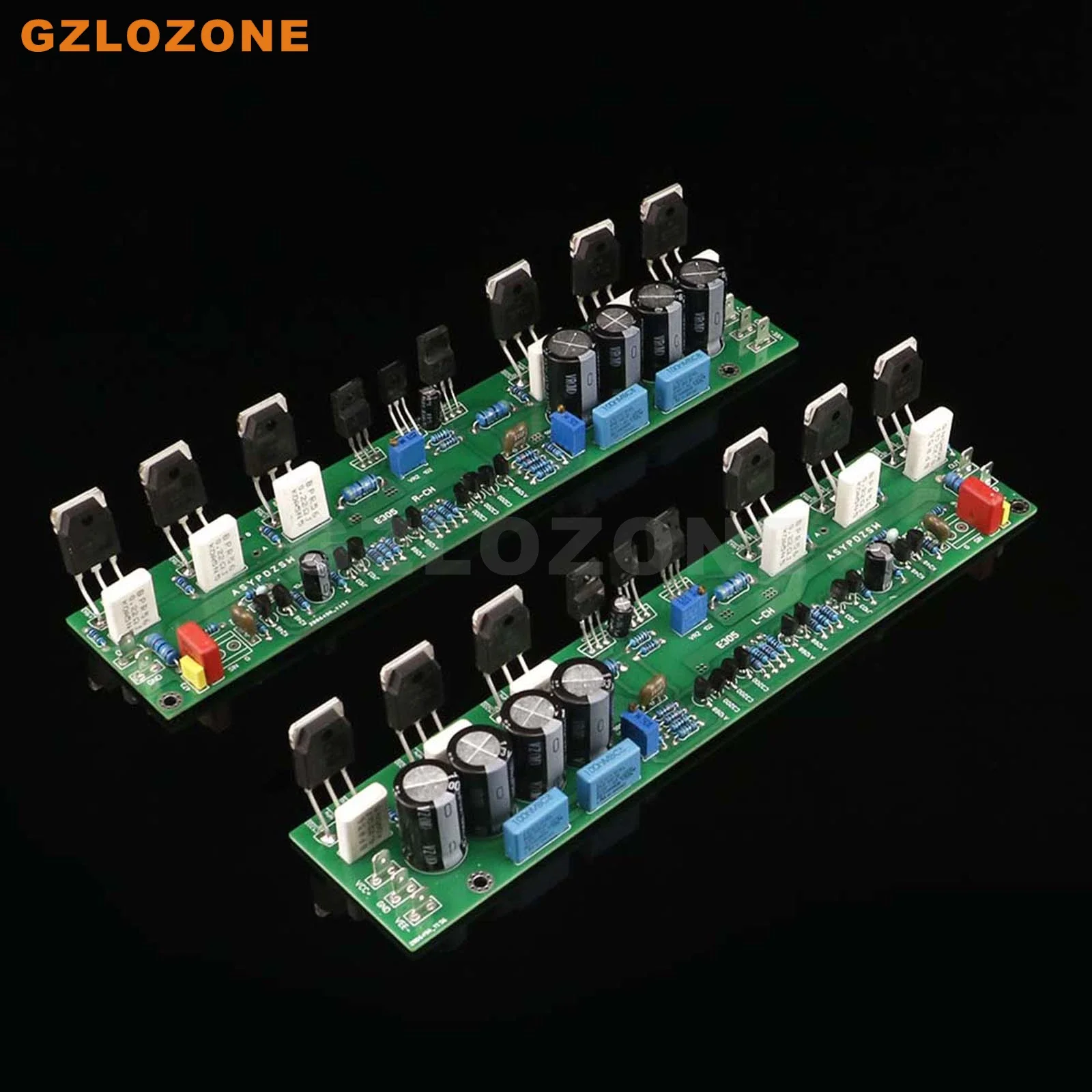
The PCB size is rectangular, which is very suitable for mounting on the heat sink, and each heat sink is equipped with a sound channel. The specific heat sink size can be installed according to the quiescent current and temperature. The default quiescent current of the finished board is 50mA (each heat sink is not less than 1.5KG).
Parameter:
Input voltage: DC +/-45V
PCB size: 230mm*49mm
Output power: 250W+250W 4 ohm, 125W+125W 8 ohm
SPK impedance: 4--8 ohm
THD+N: <0.1% DC+/-45V 4 ohm load
Frequency response: 20Hz~20kHz 3Hz~150kHz (when 1W output)
Total harmonic distortion: 0.08% (20Hz~20kHz)
Damping coefficient: 120 (8Ω, 50Hz)
Signal to noise ratio: 123dB
Gain: 128dB
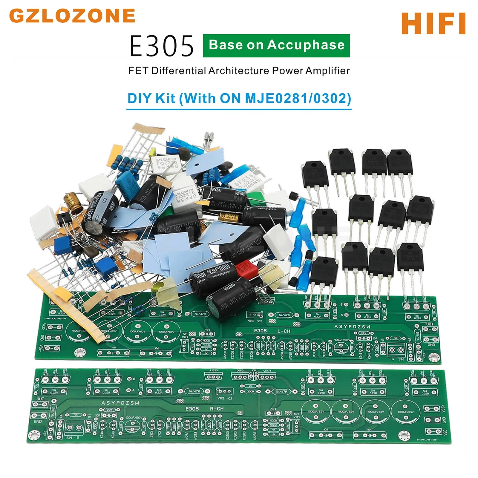
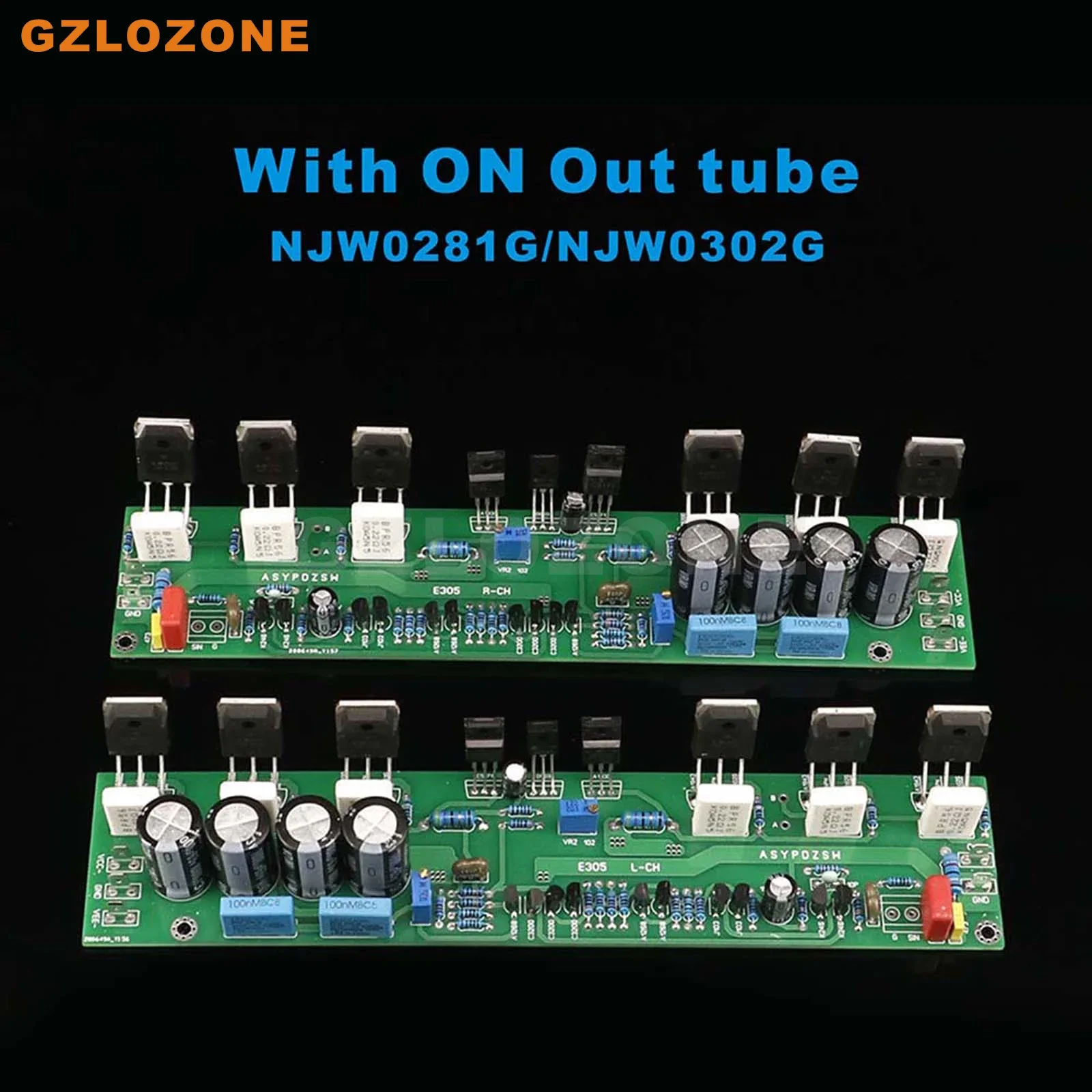
Output tube model: ON NJW02812G / NJW0302G (When you select the "Without output tubes DIY Kit" order, these tubes will not be included)
Instructions for debugging steps:
1, Quiescent current adjustment:
After welding the parts, please install them on the heat sink for debugging (note that the pipe and the heat sink should be insulated), adjust VR2 (1K adjustable resistance) to make the static current about 50mA, namely: "A" and "B" The voltage at two points is about 11mV.
2, Midpoint voltage adjustment:
Adjust VR1 (500R adjustable resistance) to make the output "OUT" and "GND" (the two ends of the output) close to 0mV; as long as the components are not installed wrongly, they can generally be adjusted to 0MV, and the maximum can also be adjusted to less than 10mV.
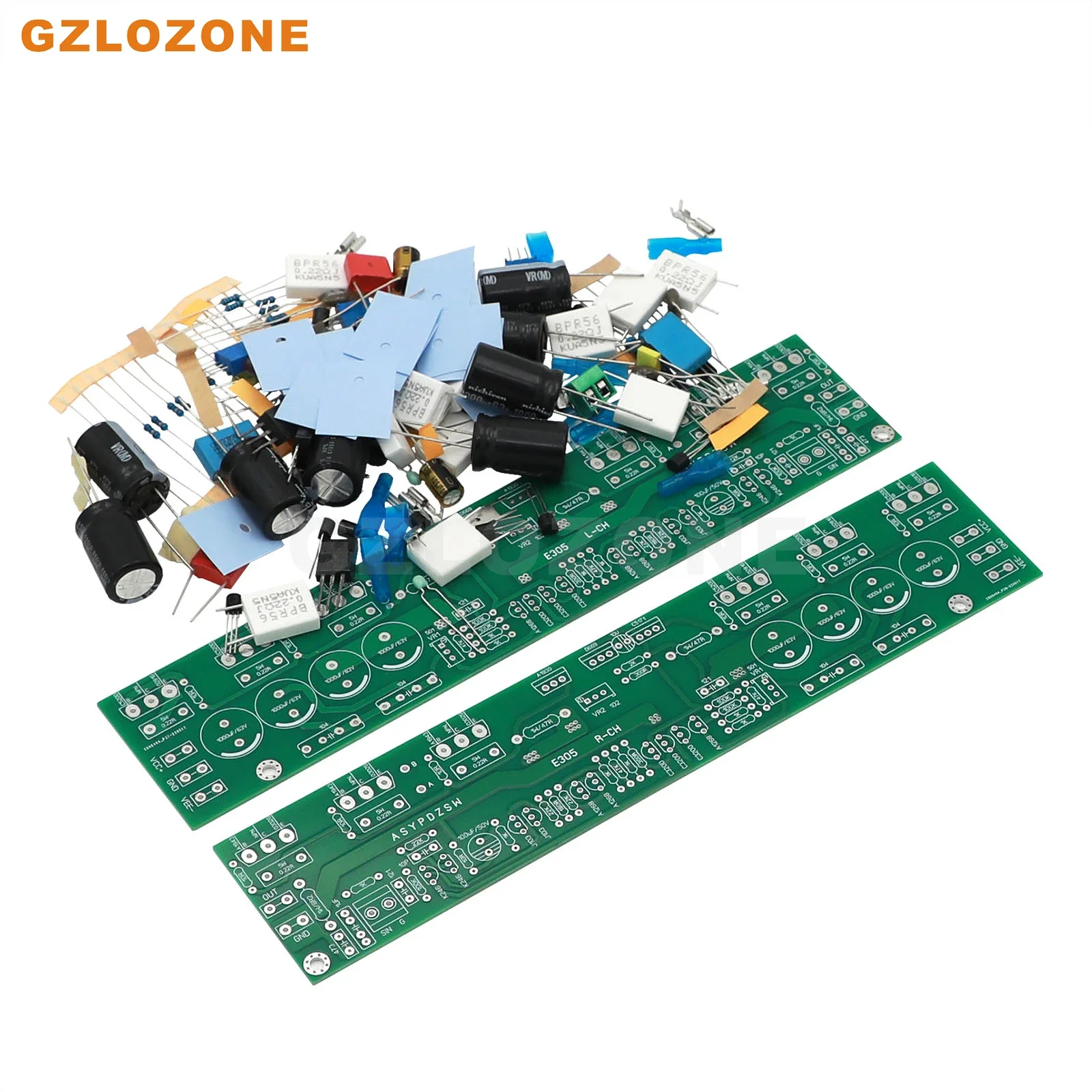
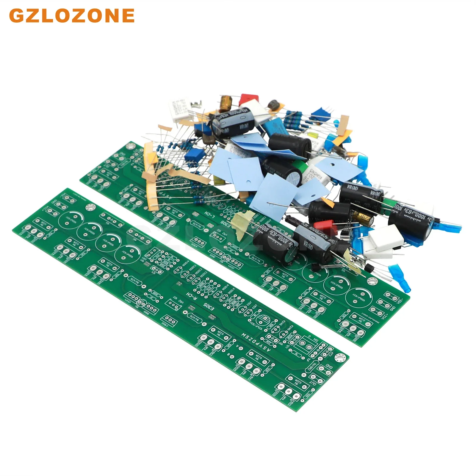
NOTE: We have Without output tubes DIY Kit or DIY kit or Finished board (Optional)

Adding to cart succeed!
items in cart.
Total:
Requires a minimum purchase of {MinPrice}. And you still need to meet the requirements.
Proceed to Checkout Return to Shopping


